Applications that use spectrometers to measure the light energy of radiant sources require an irradiance-calibration, because the uncalibrated intensity response of the spectrometer includes contributions from the spectrometer internal optics spectral transmission and detector spectral response. This application note explains how the FT-NIR Rocket 0.9-2.6 can be used for irradiance measurements over the spectral range 900-2500nm. It demonstrates how the spectral irradiance of the sun can be measured with the FT-NIR Rocket.
The Hardware needed is:
- FT-NIR Rocket spectrometer
- Calibration light source with calibration data
- Reflective cosine receiver with a 1m long optical fiber cable (type NA=0.22, core diameter 600µm)
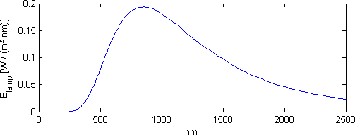
The calibration source that we are using is a 250W halogen lamp, with a calibration traceable to the Metrology Institute of Germany (PTB) whose absolute irradiance \( \mathrm{E}_\mathrm{lamp}(\lambda) \), at a distance of 30cm, is shown on Figure 1.
In order to measure calibration irradiance, the FT-NIR spectrometer is connected via an optical fiber to our reflection-mode cosine receiver. This piece of hardware is needed in order to diffuse the light at the spectrometer fiber input, as otherwise light coupling into the fiber would be too much dependant on the orientation of the optical fiber with respect to the light source.
Most manufactuers of visible spectral range fibered spectrometer are offering cosine receivers that are working in transmission mode, which are typically made of a thin layer of opaline glass or PTFE like material. While they are a good solution in the visible range, transmisson-mode cosine receivers suffer from chromatic effecs in the near-infrared: their response is no longer a cosine function of the incidence angle at near-infrared wavelength, because the diffuser becomes partially transparent as the diffraction effects decrease as \( \sim 1/ {\lambda^4} \) , according to light scattering physics. Our reflection-mode cosine receiver overcomes these limitations, offering good cosine response all over the NIR range up to 2500nm. For more information, read this article.
The reflective cosine receiver of the spectrometer fixed onto a photographic tripod and placed at the nominal distance of 30 cm from the calibration halogen lamp, as shown in Figure 2.
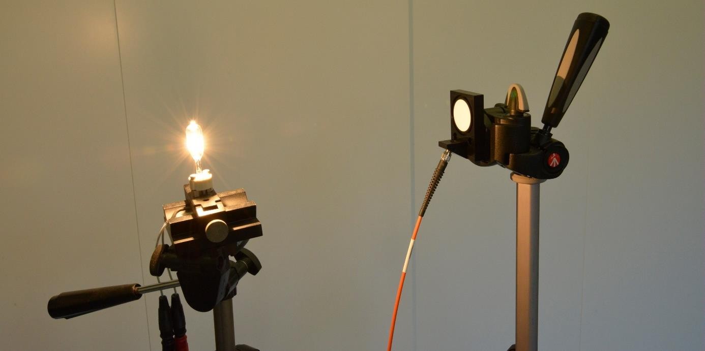
Figure 2 - Irradiance calibration set-up, including the Arcoptix Reflective Cosine Receiver
After taking a spectrum of the calibration lamp, the spectrometer responsivity \( R(\lambda_n) \) at all reported wavelengths can be calculated by a simple division:
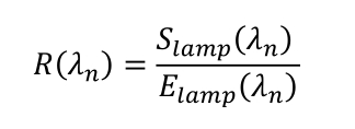
where \( S_{lamp}(\lambda_n) \) is the raw spectrum measured with the spectrometer (i.e. "counts" from the spectrometer) and \( E_{lamp}(\lambda_n) \) is the calibration lamp tabulated irradiance spectra, which must usually be re-interpolated on the spectrometer grid \(\lambda_n\).
The experimental data of the above described procedure is illustrated on Figure 3. Note that this irradiance calibration procedure is foreseen in the spectrometer software. We are showing details of the calibration only to make the calibration process easier to understand.
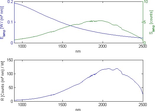
Figure 3 - Calibration of the FT-NIR with the halogen lamp. Above: calibration lamp irradiance and raw spectrum from the lamp. Below: calculated responsivity of the spectrometer.
Once the calibration procedure achieved, we have taken our hardware on the roof of our building for an outdoor measurement of the solar spectrum, as shown on Figure 4. The reflective cosine receiver, attached on the photographic tripod, was oriented towards the sun.
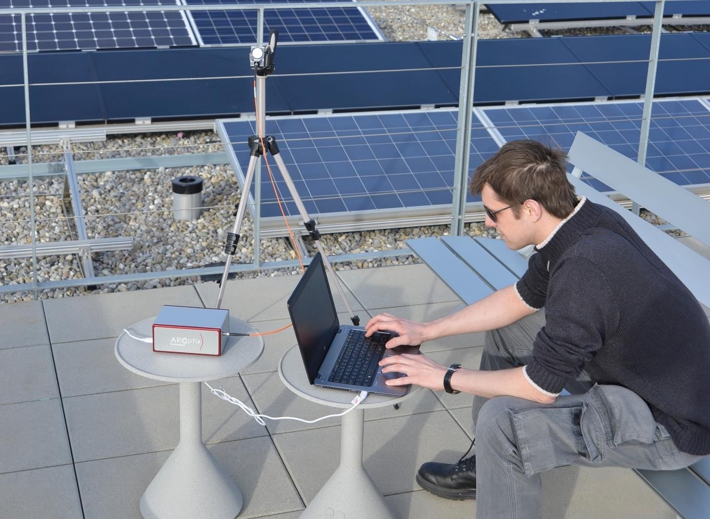
Figure 4 - Outdoor solar irradiance measurement. The spectrometer, reflective cosine receiver on a photographic tripod, and laptop computer.
The spectrometer records the raw spectrum of the sun, which is then multiplied by the spectrometer spectral responsivity to give an absolute irradiance:
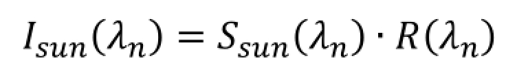
This is illustrated on Figure 5, showing the raw spectrum (above) and the absolute irradiance spectrum of the sun as measured by our system.
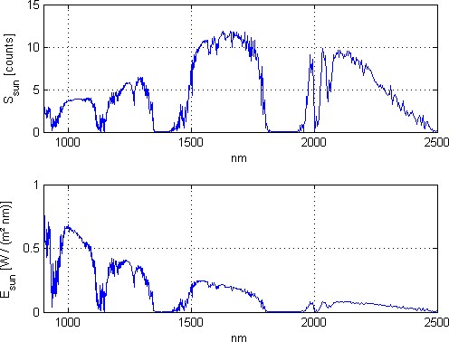
Figure 5 - Raw and calibrated solar spectrum (irradiance)
Note that the spectra is not noisy. The sharp features in the spectra are due to narrow absorption by gases and the relatively high resolution of the instrument (8cm-1). Figure 6 shows the same portion of the solar spectrum according to ASTM G173-03 (Standard Tables for Reference Solar Spectral Irradiances) which is taken at a comparable resolution (1nm up to 1700nm, and 5nm above this limit). The same spectral structures are easily identifiable.
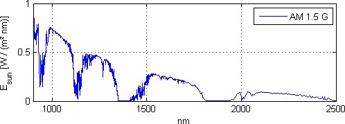
Figure 6 - Solar spectrum according to ASTM G173-03 (tilted)
